
TR7 & TR8 Forum
[Solved] TR8 Dirt Shield/Flywheel Cover Plate Install
Posted by Kimbo001


Kimbo001
Kim S
|
Topic Creator (OP)
Aug 15, 2025 10:04 PM
Joined 1 year ago
81 Posts
|
Solved
I'm a bit lost/confused regarding the install of the dirt shield into a 7 with an SD1 V8 and LT77 5-speed manual. The PO bought the wrong part, I think it's for an auto, not manual, therefore doesn't allow for the slave cylinder, and so wasn't installed at the time. I've got a correct one on order from Rimmers, but not exactly sure how to it fits - I mean, I know where it goes, and theoretically how it fits, but can't seem to find any diagrams to confirm a few things, so hoping I can get some advice.
Obviously it has 4 bolts that connect the shield to the bellhousing, but it also has two tabs at the top with holes in it, do they connect anywhere, because I can't seem to find any reference to them at all, and the TR8 workshop manual only refers to 4-bots securing the plate to the bellhousing?
And now for the really dumb question, sorry for asking and please have a good laugh at my stupidity - again, I haven't seen one installed, nor can I find any diagrams to guide me, so this is just based on gut feel. I'm hoping when the plate arrives, it'll all become clear, but right now it's not really making sense.
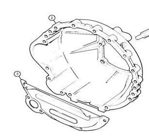
The dirt shield is obviously "shaped" and not flat - it has a kind of dome which goes on the engine side; but when you marry the block and the bellhousing together, the only way that my confused mind says that there's enough room for this to all go together is for the domed section to slide in between the flywheel and the engine block, although it's actually bolted to the bellhousing - is that right?
I've tried to draw a diagram to help explain - the dirt shield is the red line.
Obviously it has 4 bolts that connect the shield to the bellhousing, but it also has two tabs at the top with holes in it, do they connect anywhere, because I can't seem to find any reference to them at all, and the TR8 workshop manual only refers to 4-bots securing the plate to the bellhousing?
And now for the really dumb question, sorry for asking and please have a good laugh at my stupidity - again, I haven't seen one installed, nor can I find any diagrams to guide me, so this is just based on gut feel. I'm hoping when the plate arrives, it'll all become clear, but right now it's not really making sense.
The dirt shield is obviously "shaped" and not flat - it has a kind of dome which goes on the engine side; but when you marry the block and the bellhousing together, the only way that my confused mind says that there's enough room for this to all go together is for the domed section to slide in between the flywheel and the engine block, although it's actually bolted to the bellhousing - is that right?
I've tried to draw a diagram to help explain - the dirt shield is the red line.
Attachments:
Dirt shield rimmer.jpg 14.4 KB

Carb-Dave
Dave Mundt
|
Aug 15, 2025 11:14 PM
Top Contributor
Joined 7 years ago
843 Posts
|
I added this piece because I forgot to install it after the engine and transmission were installed into the car.
I needed to lower the front sub-frame about 6 inches and prop the engine up by supporting it under the front pulley/damper and leaving the transmission attached to the unibody. WIth the lowered sub-frame, you can then remove the oil pan and slave cylinder to install the dust cover. So in the end, it's a fairly involved installation. Lowering the sub-frame with the steering rack attached and the pump on the engine requires some tricky loosening to gain slack on the hoses. You'll also need to free the struts from their mounting points to lower the whole assembly.
Carb-Dave

|
Kimbo001
Kim S
|
Topic Creator (OP)
Aug 16, 2025 12:29 AM
Joined 1 year ago
81 Posts
|
In reply to # 2130709 by Carb-Dave
I added this piece because I forgot to install it after the engine and transmission were installed into the car.
I needed to lower the front sub-frame about 6 inches and prop the engine up by supporting it under the front pulley/damper and leaving the transmission attached to the unibody. WIth the lowered sub-frame, you can then remove the oil pan and slave cylinder to install the dust cover. So in the end, it's a fairly involved installation. Lowering the sub-frame with the steering rack attached and the pump on the engine requires some tricky loosening to gain slack on the hoses. You'll also need to free the struts from their mounting points to lower the whole assembly.
Carb-Dave
I needed to lower the front sub-frame about 6 inches and prop the engine up by supporting it under the front pulley/damper and leaving the transmission attached to the unibody. WIth the lowered sub-frame, you can then remove the oil pan and slave cylinder to install the dust cover. So in the end, it's a fairly involved installation. Lowering the sub-frame with the steering rack attached and the pump on the engine requires some tricky loosening to gain slack on the hoses. You'll also need to free the struts from their mounting points to lower the whole assembly.
Carb-Dave
I can understand the slave removal, but I'm presuming you needed to remove the oil pan/sump to get around the stiffening plate?
|
Kimbo001
Kim S
|
Topic Creator (OP)
Aug 16, 2025 12:32 AM
Joined 1 year ago
81 Posts
|
|
Carb-Dave
Dave Mundt
|
Aug 16, 2025 11:52 AM
Top Contributor
Joined 7 years ago
843 Posts
|

POW
Peter Wirth
|
Aug 16, 2025 11:54 AM
Top Contributor
Joined 9 years ago
9,023 Posts
|
In reply to # 2130713 by Kimbo001
LaVerne - brilliant, thanks for the photos - yes they do help - so those two upper tabs actually connect to the block - now I just need to figure out those bolt sizes LOL
Thanks guys ... Kimbo
Thanks guys ... Kimbo
Ah, regarding those bolts. This seems very weird to me but on mine the oil-pan bolts were 1/4"x28 while those shield bolts were M7 1.0. If you start with 1/4'x28 you will find they start binding after after a little bit. You can keep on a winding them into the alloy I suppose. If they go in easily enough that's probably what someone has done in the past. - Pete

Darth V8R
Vance Navarrette
|
Aug 16, 2025 07:54 PM
Top Contributor
Joined 12 years ago
6,760 Posts
|
In reply to # 2130761 by POW
Ah, regarding those bolts. This seems very weird to me but on mine the oil-pan bolts were 1/4"x28 while those shield bolts were M7 1.0. If you start with 1/4'x28 you will find they start binding after after a little bit. You can keep on a winding them into the alloy I suppose. If they go in easily enough that's probably what someone has done in the past. - Pete
In reply to # 2130713 by Kimbo001
LaVerne - brilliant, thanks for the photos - yes they do help - so those two upper tabs actually connect to the block - now I just need to figure out those bolt sizes LOL
Thanks guys ... Kimbo
Thanks guys ... Kimbo
Ah, regarding those bolts. This seems very weird to me but on mine the oil-pan bolts were 1/4"x28 while those shield bolts were M7 1.0. If you start with 1/4'x28 you will find they start binding after after a little bit. You can keep on a winding them into the alloy I suppose. If they go in easily enough that's probably what someone has done in the past. - Pete
The engine itself and all its fasteners are imperial (SAE). Anything that touches the transmission (including the bell housing) is metric. So the bolts for the sump/engine block are imperial, the bolts for the bell housing are metric. This means the dirt shield has two SAE bolts, and four metric.
Vance
1980 Platinum Metallic TR8, frame off restoration, complete.
1974 Jensen Healey, now assembled and awaiting startup. =:-)
|
Kimbo001
Kim S
|
Topic Creator (OP)
Aug 16, 2025 09:50 PM
Joined 1 year ago
81 Posts
|
Vance - thanks, and naturally, almost as soon as Dave posted his reply, the Rimmer "AI" decided to show me the diagram with the two upper bolts and their sizes - I'm sure it listens somehow and then modifies the diagram dynamically to add the "missing" content - which of course it doesn't - but following the rabbit down another hole led me back to the place I started at, and with a flourish it showed me what had always been there, but I hadn't noticed  The old adage "can't see the wood for the trees" springs to mind.
So, FYI, the dirt shield to bellhousing bolts are M6 x 16mm, and the dirt shield to block are 5/16 UNC x 5/8.
And after this discussion I've realised that the dirt shield sits between the flywheel and block, and gets attached to the block first, and then bolted up to the bellhousing when the two are put together - which now makes perfect sense - based on the diagram, I was trying to figure out how it was gonna work if you did it the other way, which of course it never would, doh !!
Thanks gents
The old adage "can't see the wood for the trees" springs to mind.
So, FYI, the dirt shield to bellhousing bolts are M6 x 16mm, and the dirt shield to block are 5/16 UNC x 5/8.
And after this discussion I've realised that the dirt shield sits between the flywheel and block, and gets attached to the block first, and then bolted up to the bellhousing when the two are put together - which now makes perfect sense - based on the diagram, I was trying to figure out how it was gonna work if you did it the other way, which of course it never would, doh !!
Thanks gents
|
Aug 19, 2025 07:36 PM
Joined 2 years ago
7 Posts
|
|
Hi Kimbo
I am upgrading my TR7 to V8 spec, using a 3.9 L Rover V8 and an LT77 five speed gearbox.
I purchased a new bellhousing and dirt shield from Rimmer Bros mid 2024, expecting everything to go together as designed. Not so simple. Test fitting the dirt shield on the bellhousing by itself went well. Trying to slide the dirt shield into position with the bellhousing and engine connected didn't work, even after removing the reinforcing strap across the rear of the sump. We had to reduce the height of the shield by 3 mm, just underneath the top fold, and to elongate the slots in the top fold (the horizontal flange) to match the bolt holes in the block.
I contacted Rimmer Bros when we first encountered the problem, but they were not of any help. I suspect that during the remanufacturing stage of the dirtshield, there was confusion between the edge and centre of the 6 mm holes, as the major error was 3.0 mm.
My welding friend cut out a 3 mm slice below the upper flange, after first scribing alignment marks. He then gave it back after tacking the pieces back together to test the fit, and then did an almost invisible weld across the whole seam to finish his part of the job. My son then repainted the part before the final fit.
It is not necessary to remove the sump, but is necessary to remove the reinforcing strap across the rear of the sump, and to remove one of the exhaust headers to allow enough room to slide the shield into position. Thin fingers required, and thin sockets on a 1/4" extension to refit the bolts for the reinforcing strap, as the bulges in the dirt shield tend to get in the way.
With hindsight we should have sorted all this out before fitting the engine and gearbox to the body.
I confirm Vance's previous comment that the bolts engaging with the engine are UNC and those engaging with the bellhousing are metric (including the 8 mm bolts for the slave cylinder).
|
Kimbo001
Kim S
|
Topic Creator (OP)
Aug 21, 2025 04:48 AM
Joined 1 year ago
81 Posts
|
In reply to # 2131473 by pjh889
Hi Kimbo
I am upgrading my TR7 to V8 spec, using a 3.9 L Rover V8 and an LT77 five speed gearbox.
I purchased a new bellhousing and dirt shield from Rimmer Bros mid 2024, expecting everything to go together as designed. Not so simple. Test fitting the dirt shield on the bellhousing by itself went well. Trying to slide the dirt shield into position with the bellhousing and engine connected didn't work, even after removing the reinforcing strap across the rear of the sump. We had to reduce the height of the shield by 3 mm, just underneath the top fold, and to elongate the slots in the top fold (the horizontal flange) to match the bolt holes in the block.
I contacted Rimmer Bros when we first encountered the problem, but they were not of any help. I suspect that during the remanufacturing stage of the dirtshield, there was confusion between the edge and centre of the 6 mm holes, as the major error was 3.0 mm.
My welding friend cut out a 3 mm slice below the upper flange, after first scribing alignment marks. He then gave it back after tacking the pieces back together to test the fit, and then did an almost invisible weld across the whole seam to finish his part of the job. My son then repainted the part before the final fit.
It is not necessary to remove the sump, but is necessary to remove the reinforcing strap across the rear of the sump, and to remove one of the exhaust headers to allow enough room to slide the shield into position. Thin fingers required, and thin sockets on a 1/4" extension to refit the bolts for the reinforcing strap, as the bulges in the dirt shield tend to get in the way.
With hindsight we should have sorted all this out before fitting the engine and gearbox to the body.
I confirm Vance's previous comment that the bolts engaging with the engine are UNC and those engaging with the bellhousing are metric (including the 8 mm bolts for the slave cylinder).
I am upgrading my TR7 to V8 spec, using a 3.9 L Rover V8 and an LT77 five speed gearbox.
I purchased a new bellhousing and dirt shield from Rimmer Bros mid 2024, expecting everything to go together as designed. Not so simple. Test fitting the dirt shield on the bellhousing by itself went well. Trying to slide the dirt shield into position with the bellhousing and engine connected didn't work, even after removing the reinforcing strap across the rear of the sump. We had to reduce the height of the shield by 3 mm, just underneath the top fold, and to elongate the slots in the top fold (the horizontal flange) to match the bolt holes in the block.
I contacted Rimmer Bros when we first encountered the problem, but they were not of any help. I suspect that during the remanufacturing stage of the dirtshield, there was confusion between the edge and centre of the 6 mm holes, as the major error was 3.0 mm.
My welding friend cut out a 3 mm slice below the upper flange, after first scribing alignment marks. He then gave it back after tacking the pieces back together to test the fit, and then did an almost invisible weld across the whole seam to finish his part of the job. My son then repainted the part before the final fit.
It is not necessary to remove the sump, but is necessary to remove the reinforcing strap across the rear of the sump, and to remove one of the exhaust headers to allow enough room to slide the shield into position. Thin fingers required, and thin sockets on a 1/4" extension to refit the bolts for the reinforcing strap, as the bulges in the dirt shield tend to get in the way.
With hindsight we should have sorted all this out before fitting the engine and gearbox to the body.
I confirm Vance's previous comment that the bolts engaging with the engine are UNC and those engaging with the bellhousing are metric (including the 8 mm bolts for the slave cylinder).
Good stuff mate, thanks. I’ve not put the donk back in yet AND it’s separate from the transmission, so hopefully things fingers are not required. However good info about the fit of the Rimmers shield. I’ll let you know how I get on, once it arrives �
about 2 weeks and 19 hours later...
|
Kimbo001
Kim S
|
Topic Creator (OP)
Sep 5, 2025 12:36 AM
Joined 1 year ago
81 Posts
|
In reply to # 2131473 by pjh889
Hi Kimbo
I am upgrading my TR7 to V8 spec, using a 3.9 L Rover V8 and an LT77 five speed gearbox.
I purchased a new bellhousing and dirt shield from Rimmer Bros mid 2024, expecting everything to go together as designed. Not so simple. Test fitting the dirt shield on the bellhousing by itself went well. Trying to slide the dirt shield into position with the bellhousing and engine connected didn't work, even after removing the reinforcing strap across the rear of the sump. We had to reduce the height of the shield by 3 mm, just underneath the top fold, and to elongate the slots in the top fold (the horizontal flange) to match the bolt holes in the block.
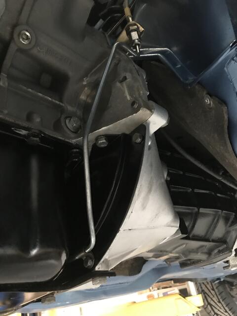
Yep - same problem with mine - a right royal pain in the 'arris - fortunately, having your experience in hand, I've been doing the test fitting on the garage floor. Only had to remove one sump bolt - on the left hand side looking forwards - and lean gently on the bracing strap to get enough room to slid it in. I'll give feedback to Rimmer Bros as well, FWIW.
about 1 week and 22 hours later...
|
Kimbo001
Kim S
|
Topic Creator (OP)
Sep 12, 2025 11:32 PM
Joined 1 year ago
81 Posts
|
So to finish this thread off, I've finally got the damn shield sorted out. As Pete said, above, the Rimmer's unit was too tall and the bolts connecting to the block were in the wrong position - I did provide some feedback to their customer service email, but (kind of) as expected, not even so much a "thank you for contacting us...." reply. However, it is what it is...
Anyway last weekend, after several attempts to enlarge holes, I did actually get the plate to fit , kind of, but wasn't happy with those stupid little tabs on the top connecting it to the block, as they didn't really hold it in place - every time you breathed the damn thing fell off/came loose. So I bit the bullet - fabricated up two new tabs out of some square tube, took an angle grinder and cut the plate, just under the top lip and tabs. Then slipped the bastardized plate it into place, but not bolted, connected up the bellhousing, bolted the plate to the bell housing, then bolted the tabs to the block, epoxy-ed the tabs to the plate, and left it.
Today, I disconnected the bellhousing, took the plate out, with the tabs still glued in place, they did need a bit of extra grinding down for clearance, and welded them up, then sprayed with engine enamel. Apart from the pigeon poo welding - I'd bought a MIG which I'd never used before (had a stick/ARC previously and was pretty crap with that as well ) - I think overall it came out all right, and it fits perfectly. Very happy. Now on to the next challenge....
Anyway last weekend, after several attempts to enlarge holes, I did actually get the plate to fit , kind of, but wasn't happy with those stupid little tabs on the top connecting it to the block, as they didn't really hold it in place - every time you breathed the damn thing fell off/came loose. So I bit the bullet - fabricated up two new tabs out of some square tube, took an angle grinder and cut the plate, just under the top lip and tabs. Then slipped the bastardized plate it into place, but not bolted, connected up the bellhousing, bolted the plate to the bell housing, then bolted the tabs to the block, epoxy-ed the tabs to the plate, and left it.
Today, I disconnected the bellhousing, took the plate out, with the tabs still glued in place, they did need a bit of extra grinding down for clearance, and welded them up, then sprayed with engine enamel. Apart from the pigeon poo welding - I'd bought a MIG which I'd never used before (had a stick/ARC previously and was pretty crap with that as well
) - I think overall it came out all right, and it fits perfectly. Very happy. Now on to the next challenge....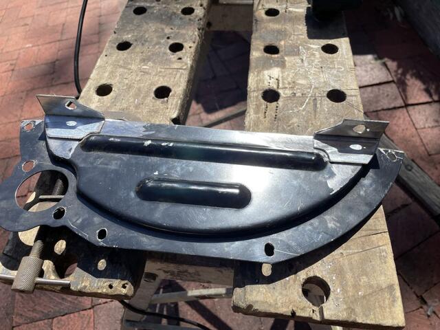
Having trouble posting or changing forum settings?
Read the Forum Help (FAQ) or click Contact Support at the bottom of the page.
