A collection of service tips and bulletins from the Triumph Motor Company, 1970.
TR-4A
We have received reports from our field representatives indicating that difficulty is experienced in some instances with the hood of the TR-4A becomming "jammed" in the closed position. Should you encounter such a case, you will find the adoption of the following procedure will en- able relatively easy access to the hood lock:
1. Remove the 8 screws securing the glovebox and remove the glovebox.
2. Remove the rubber grommet located directly behind the glovebox where the heater control cable passes through the bulk head.
3. By maneuvering a long screwdriver or similar tool, the under side of the hood lock release mechanism can be operated.
In most cases, the approximate time involved is 30 minutes.
A modification to avoid this condition was introduced from CT 58700 onward.
TR-6
Difficulty is sometimes experienced with gear lever chatter. In fact, this remedy will apply to all of the TR range, example: 4A, 250 and TR-6.
With the vehicle on a lift, or alternatively suitably raised off the floor, take a handful of heavy bearing grease and pack the gearbox gate where the lever ball end is inserted. While this remedy will not last for an indefinite period, it will effect relief at least between servicing intervals.
Cold Starting
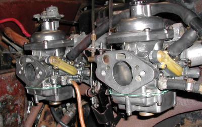
At the introduction of the Stromberg C.D.S.E. type carburetor, difficulty was experienced in some cases of poor starting in colder areas. It was found that a simple adjustment to the carburetors would overcome this problem.
The C.D.S.E. type carburetors are equipped with a choke control limiting device. This control takes the form of a spring loaded plunger which is part of the carburetor starter box cover assembly. The plunger itself is located at the rear of each carburetor adjacent to the air cleaner, and can be easily identified as it is made of brass and has a slotted head with serrated edges.
For summer operation, the plunger should remain with the slotted head in the vertical position. For winter operation the slot should be in the horizontal position, thus allowing a little extra choke movement.
In January of 1969 the radiator pressure on all Triumph cars was increased from 7 P.S.I. to 13 P.S.I. The only visible difference between the 13 pound pressure system and a 7 pound pressure system is in the radiator cap itself, however, if owners wish to increase the pressure in any cars built prior to January of 1969 it is also necessary that they replace the water pump seal. This seal has been modified to accommodate the higher operating pressure, and, therefore, severe water leakage would be experienced if the seal is not replaced.
Remember it is also necessary to replace the temperature sender unit as this item is also sensitive to pressure and if left unattended would result in an erroneous reading.

Triumph GT6 Stromberg CDSE Carburetors
Wire Wheels
The fitting procedure of wire wheels has been revised, and it is of paramount importance that owners adhere to the following instructions.
This procedure must be adopted if the wheels are removed and are refitted, and careful attention always given to this at all routine service operations:
1. Check that the splines on the hub adaptor and in the wheels are clean and free of foreign matter.
2. Insure that the adaptor taper, hub nut and mating wheel hub tapers are clean.
3. Grease all tapers, splines and screw threads liberally with special PBC grease. This grease is available in one ounce tubes from your Triumph dealer as part number V 640.
4. Slide the wheel on to the adaptor and pushing against the wheel hub center to maintain concentric location, simultaneously screw on the retaining nut by hand until the wheel is felt to seat on adaptor taper.
Restraining the wheel with one hand, continue tightening by striking the ears of the nut with a soft faced hammer or on later cars, tighten wheel nut with special wrench included with tool kit. Lower the wheel to the ground and finally tighten.
While on the subject of PBC grease, this substance is very useful for several applications. One point where it is advantageous is on the back of the front brake pads and where fitted the anti-squeal shims. You will find that brake squeal, particularly annoying on TR-6 models, can be eliminated in most cases.
Gearbox Assembly
For those owners who undertake the more difficult task of dismantling the gearbox, it will be found advantageous upon reassembling to assemble the main shaft prior to installing in the gearbox casing.
Take the top cover assembly and make sure it is in the neutral position. Offer up the top cover selector forks to the appropriate selector hubs. If you find that the selector forks do not drop right into place, then obviously you have assembled the main shaft incorrectly. It is, however, much simpler to discover the fault at this stage for obviously once you have installed the main shaft assembly in the casing it would entail withdrawing the bearings and going through a lengthy dismantling procedure over again.
GT-6+ Accelerator Linkage

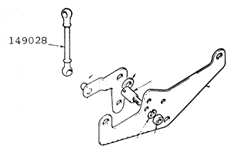
Some difficulty has been experienced in obtaining a smooth progressive movement of the accelerator pedal relative to throttle opening on the GT-6+.
An improvement in this condition can be made by removing the connecting rod (part number 149028) which joins the bell crank lever and the carburetor spindle cross shaft, removing one ball and reducing the total length of the rod by 3/8", re-cutting the thread and replacing the ball end to give a dimension of 2.75" to the centers of the ball ends.
The original dimension of the connecting rod was 3.12" to the centers of the ball ends. The new dimension of 2.75" was introduced at approximate commission number KC 55500.
→ More information on the GT-6+ Accelerator Linkage can be found by clicking here


Want to leave a comment or ask the owner a question?
Sign in or register a new account — it's free