Having duly received the 676-000 bushings from Moss Motors for the TR6 accelerator shaft, along with the supplemental information & instructions, I thought to myself surely there has to be another way, over and above what was outlined in the instructions, of installing these bushings.
After a lifetime of being a mechanic, I have beaten myself up pretty badly, bruised knuckles, crooked neck, back spasms and all the other kind of ailments not withstanding, my hope was that I wasn't going to find myself suffering once again.
Now, I can not believe that I am the only person who came up with the idea of cutting the accelerator shaft into two pieces (to make it easier for removal and refitting), then threading the ends and joining them back together again. So forgive me if someone out there has come up with the same idea before.

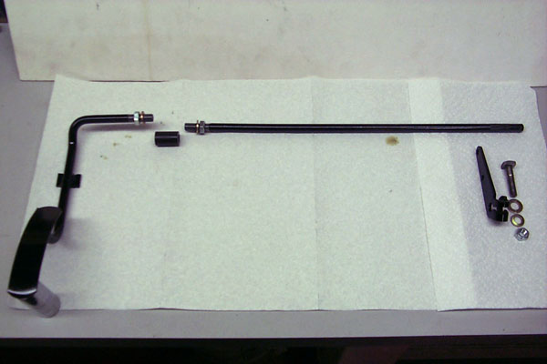
Layout of Triumph TR6 accelerator shaft components, from rear to front
Before cutting the shaft with a small hacksaw, I scribed matching lines on either side of the cut; this would be our reference point during refitting. Once the cut was made, the gas pedal shaft section was removed, as was the long shaft section complete with the carb linkage control lever.
With the two sections of the shaft now removed, the scribe lines were extended back for about 1.5" at which point they were center punched. The carb linkage control lever was also center punched relative to the longer section of the shaft.
Since the accelerator shaft was 3/8" OD, the two sections of shaft were then threaded 3/8" SAE to a depth of 1".
Next, a 5/8" OD x 1" connector, made from 5/8" OD round steel bar, was drilled and tapped to the same thread. This connector was then checked for free run on the male threads. Appropriate size washers and 3/8" SAE jam nuts complemented the assembly.
All shaft components were then bead blasted and painted.
Next up was to install the bushings, which by far was the hardest part of the whole job. The bushings were softened in boiling hot water numerous times and coated with lubricant. Try as I could, I could not install from the engine compartment side. I would estimate it took a couple of hours (sore fingers) to finally get them into place from inside the car.
The bushings were further lubricated and the gas pedal assembly placed into position first. The 3/8" jam nut and flat washer were fitted to the shaft along with the connector, which was screwed onto the shaft approximately 1/2".
The long section of shaft, along with the 3/8" SAE jam nut and washer, was then inserted into the second bushing for support. The shaft was then screwed into the connector and, with the reference punch marks aligned, both 3/8" SAE jam nuts tightened.
The whole shaft assembly was then moved towards the drivers side and the carb control lever installed as per the original reference center punched marks.
The shaft assembly was inserted back into the bushing and the washer and cotter pin installed from inside.
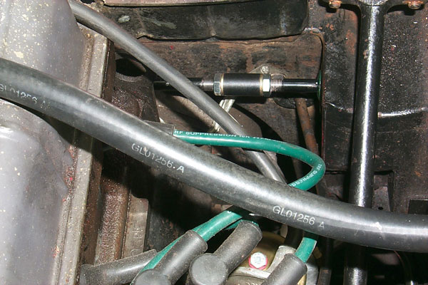
In the photograph that follows, you can see that the accelerator shaft is cosmetically acceptable and almost looks like a factory install.

Photo of modified Triumph TR6 accelerator shaft installation
I am kind of a resilient guy when it comes to battling with British cars, and I cannot recall ever turning over a job to someone else because the job had me beat. However, I came very close to throwing in the towel this time!


kevin
kevin
Want to leave a comment or ask the owner a question?
Sign in or register a new account — it's free